
An RJ45 connector has 8 pins and two standard wiring orders: T568A and T568B. The only difference is that the orange pair and the green pair swap positions. In practice, almost everyone uses T568B — T568A is a legacy standard left over from US government and military wiring. For a normal Ethernet cable, both ends must use the same order.
This guide covers every pin, what signal each one carries, why 100 Mbps only uses 4 of the 8 wires, and a 6-step crimping walkthrough with real photos — including the mistakes that make a cable fail.
Is an RJ45 Actually an RJ45?
Strictly speaking, no. The connector we plug Ethernet cables into is an 8P8C connector — “8 position, 8 contact.” True “RJ45” is a telephone standard (RJ45S) with a different keying. The industry started calling 8P8C “RJ45” anyway, and the name stuck.
The difference matters once: an RJ11 phone plug (6P4C) physically fits into an RJ45 jack but will not lock, because it has fewer positions. The name is informal, but every datasheet and every tool uses it, so we use it too.
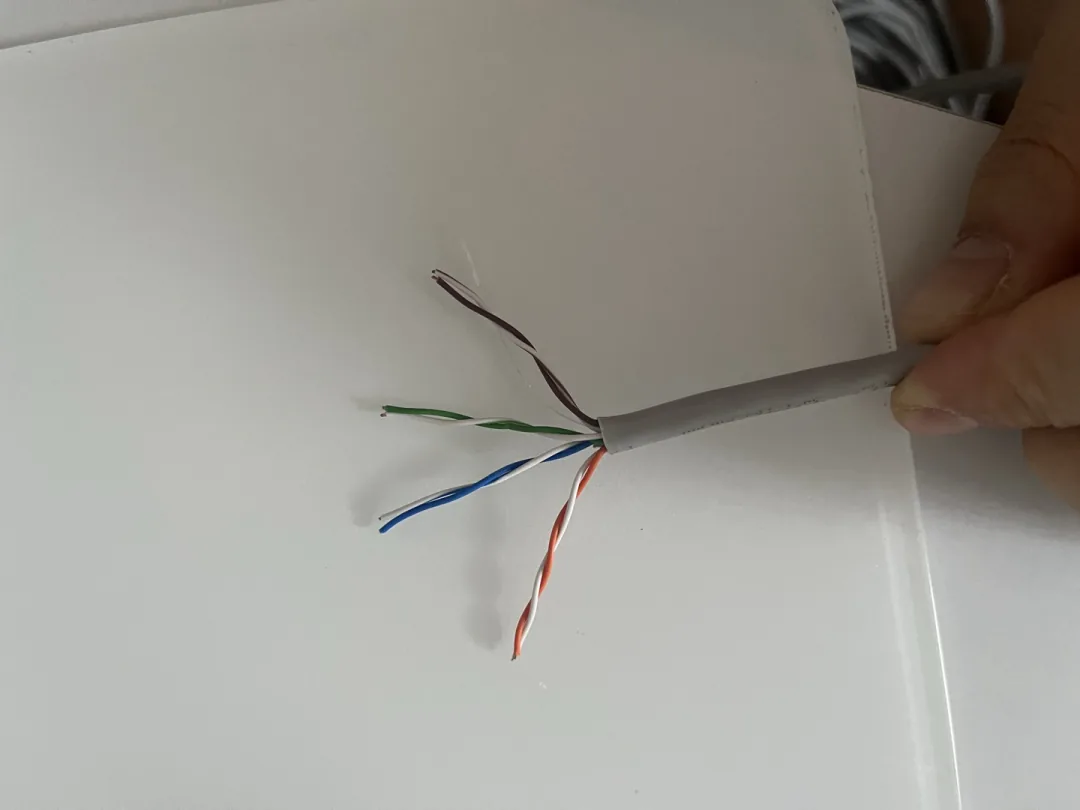
Inside the jacket are four twisted pairs:
| Pair | Solid wire | Striped wire | What the stripe looks like |
|---|---|---|---|
| 1 | Blue | White/blue | White wire with a blue stripe |
| 2 | Orange | White/orange | White wire with an orange stripe |
| 3 | Green | White/green | White wire with a green stripe |
| 4 | Brown | White/brown | White wire with a brown stripe |
The “white/color” wire is mostly white with a colored stripe. Some cables make the stripe so thin it is hard to see in low light — hold it next to the solid color and compare before you crimp.
T568A vs T568B: The Full Pinout Table
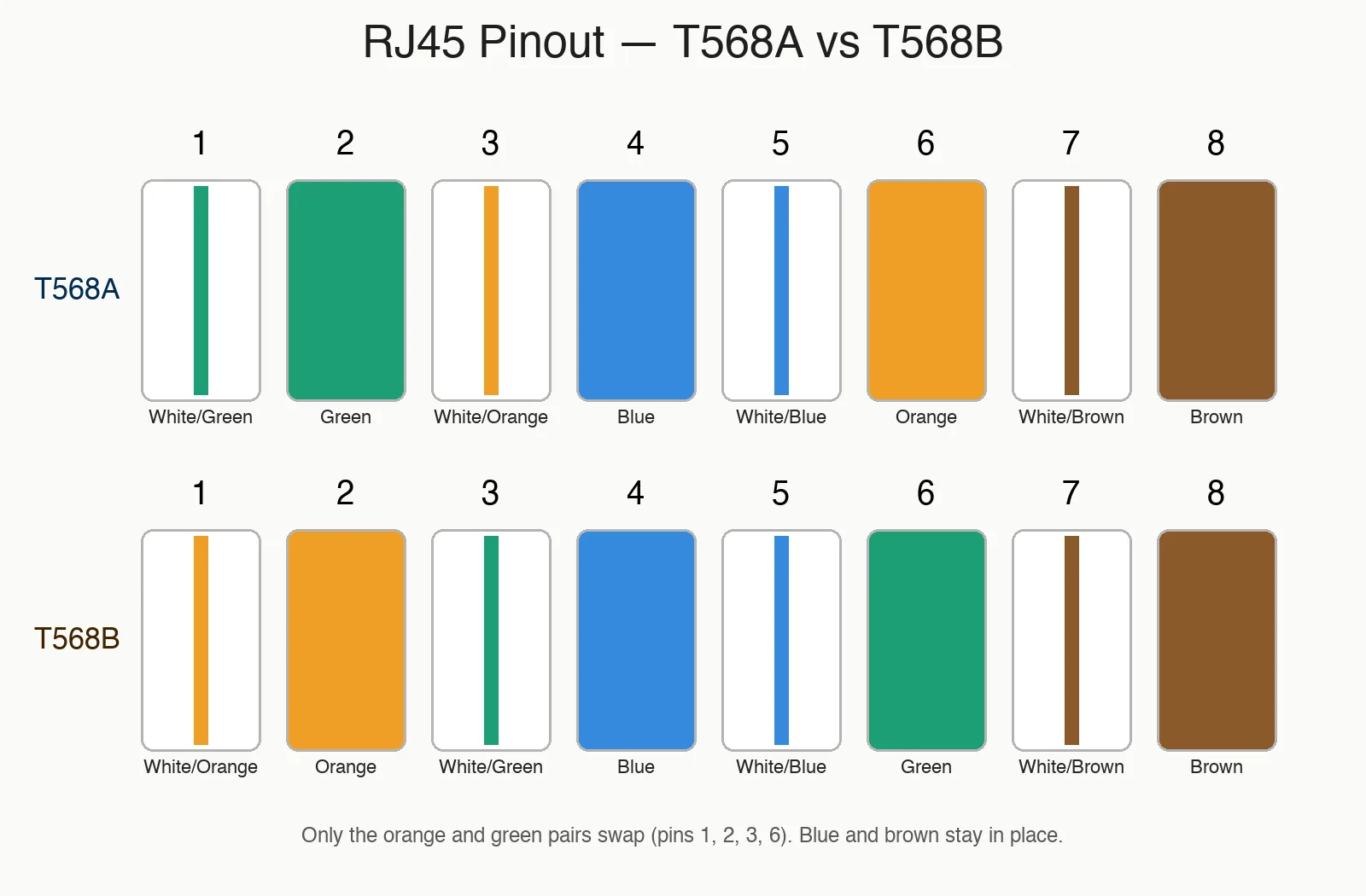
This is the table the whole guide is built around. It is a real HTML table you can copy, not a screenshot — and it shows every pin, both standards, the signal name, and whether 100 Mbps and Gigabit use it.
| Pin | T568A | T568B | Signal @100BASE-TX (10/100 Mbps) |
Signal @1000BASE-T (Gigabit) |
|---|---|---|---|---|
| 1 | White/green | White/orange | TX+ | BI_DA+ |
| 2 | Green | Orange | TX− | BI_DA− |
| 3 | White/orange | White/green | RX+ | BI_DB+ |
| 4 | Blue | Blue | — | BI_DC+ |
| 5 | White/blue | White/blue | — | BI_DC− |
| 6 | Orange | Green | RX− | BI_DB− |
| 7 | White/brown | White/brown | — | BI_DD+ |
| 8 | Brown | Brown | — | BI_DD− |
Why the signal names change: 100BASE-TX uses only two pairs — one transmits, one receives, so pins 1/2 are TX and 3/6 are RX. 1000BASE-T drives all four pairs in both directions at once, so every pin is bidirectional; the IEEE 802.3ab names them BI_DA through BI_DD instead. Same eight wires, different electrical mode.
Which pair is which: in T568 wiring the pair numbers do not run in pin order. Pair 1 is the blue pair on pins 4 and 5, pair 2 is orange on 1 and 2, pair 3 is green on 3 and 6, pair 4 is brown on 7 and 8. That is why BI_DC (pair 1) lands on pins 4/5 while BI_DB (pair 3) lands on 3/6.
Three things to notice:
- Only the orange and green pairs move. The blue and brown pairs sit in exactly the same place in both standards.
- B has orange on pins 1–2 and green on 3–6; A is the reverse. That is the whole difference.
- Both ends must match. One end A and one end B makes a crossover cable (covered later).
Why does everyone use B? The two standards have a messy history. T568B traces back to AT&T’s old 258A wiring scheme, which was already in millions of buildings when the TIA/EIA committee wrote the formal standard in 1991. The committee nominated T568A, but the market kept installing what was already familiar — 258A, renamed T568B. So B became the de facto standard even though A is the “official” one. Every pre-made cable you buy follows B. If you only learn one, learn B.
What Each of the 8 Pins Does
Pins 1, 2, 3 and 6 carry data at 100 Mbps. Pins 4, 5, 7 and 8 sit idle at 100 Mbps and only come alive at Gigabit.
Two of those signals are worth understanding, because they explain why a cable either works or mysteriously doesn’t:
- TX+ / TX- (pins 1 and 2) — “transmit.” This is the pair your device sends data out on. The + and – are a differential pair: both wires carry the same signal, one inverted, so that interference picked up along the cable cancels out at the receiver. That is why the pair must stay twisted — untwist it too far and the cancellation stops working.
- RX+ / RX- (pins 3 and 6) — “receive.” The pair your device listens on. A straight-through cable connects your device’s TX pair to the other device’s RX pair, and vice versa. If you wire one end to the wrong standard, the TX pair lines up with the other end’s TX pair instead of its RX — a crossover cable.
- BI_D3 and BI_D4 (pins 4, 5, 7, 8) — “bidirectional data.” Gigabit transmits and receives on all four pairs at once, so these two spare pairs become active data lanes. A cable that passes 100 Mbps but fails Gigabit almost always has a fault on one of these pairs.
| Speed | Pins used | Mode |
|---|---|---|
| 10/100 Mbps (100BASE-TX) | 1, 2, 3, 6 | One pair transmits, one pair receives |
| 1000 Mbps (1000BASE-T) | All 8 | Four pairs, bidirectional simultaneously |
| 2.5G / 5G / 10G | All 8 | Same 8 wires, higher frequency |
This is why a cable with two broken wires can still pass 100 Mbps but fail Gigabit: if the break is on pins 4/5 or 7/8, the cable negotiates down. Power over Ethernet (PoE) also uses these spare pairs — 4/5 and 7/8 — so a partially broken cable can drop a camera or access point even when data still flows.
Physical Specs of an 8P8C Connector
These numbers come from public manufacturer datasheets (Amphenol and Panduit) and are worth knowing if you buy connectors in bulk.
| Parameter | Typical value |
|---|---|
| Mating cycles (insertion life) | ~750 cycles |
| Supported wire gauge | 24–26 AWG solid (23 AWG is a tight squeeze) |
| Contact plating | 3µ”, 6µ”, 15µ”, 50µ” gold — 15µ” and up survives repeated plugging |
| Flammability rating | UL94 V-0 |
The gold plating number is the one that separates a connector that lasts from one that flakes. Cheap connectors are 3µ”. If you unplug a cable daily, spend a little more for 15µ” or 50µ”.
Inside the Connector: How the Contact Bites
Three things hold a crimped cable together. The gold contact pierces the insulation and bites into the copper core — it is not soldered. The latch (the plastic tab) is the only thing keeping the plug seated. On shielded connectors, a metal shell drains to ground. If the contact does not bite deep enough, the cable fails the moment you pull on it.
How to Crimp an RJ45: 6 Steps With Photos
You need a crimper, RJ45 plugs, and a cable tester. Budget about 10 minutes for your first cable, 2 minutes once you have done a few.
Step 1 — Strip the outer jacket
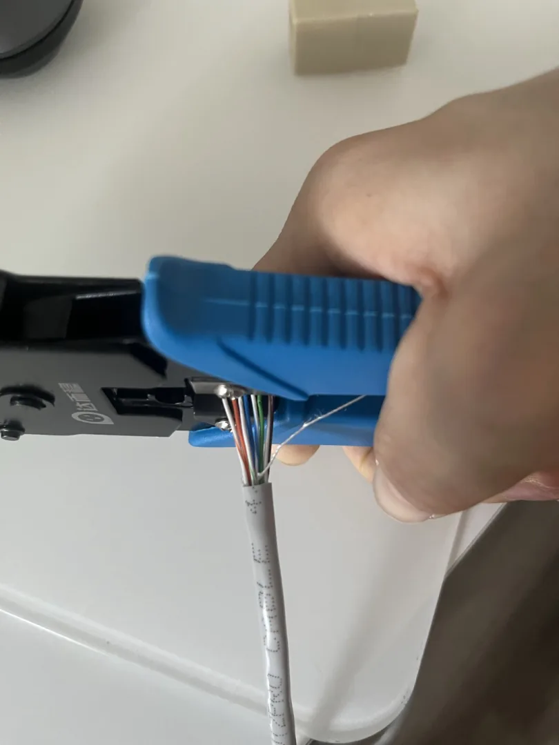
Strip off about 25 mm of the outer jacket. Use the round notch on your crimper if it has one; a sharp knife works if you are careful not to nick the inner wires. Why 25 mm: strip less and you cannot untwist the pairs enough to lay them flat; strip more and the excess has to be trimmed off anyway, which wastes wire and lets the pairs untwist further than they should. A nicked wire breaks later under stress, so cut the jacket, not the copper.
Step 2 — Untwist and arrange the pairs
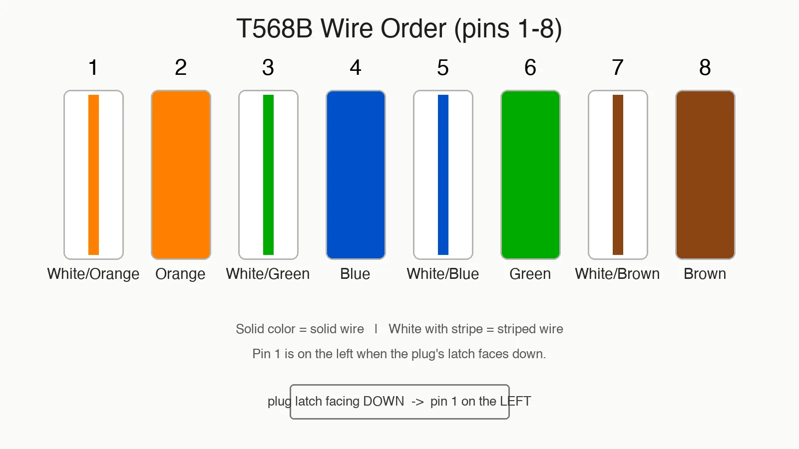
Untwist each pair and lay the eight wires flat in T568B order: white/orange, orange, white/green, blue, white/blue, green, white/brown, brown. Untwist as little as possible — keeping the twist tight is what fights crosstalk. Keep the untwisted section under 13 mm; every extra millimeter of untwisted wire raises crosstalk and costs you speed over long runs.
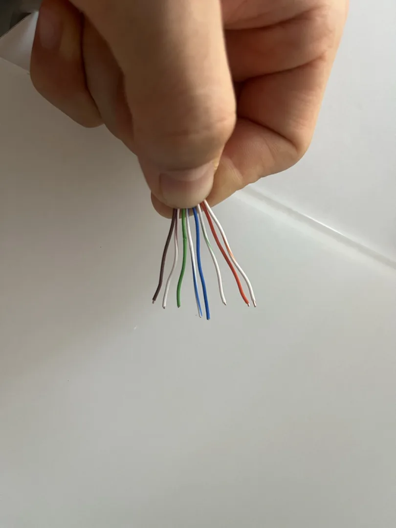
Step 3 — Trim the wires straight
Straighten the wires and cut them flat so about 12 mm remains beyond the jacket. This is the number that makes the difference: too long and the jacket will not reach into the plug, too short and the contacts cannot bite. Cut once, cleanly, with all eight ends even. If the ends are uneven, the short wires will not reach the front of the plug even after the long ones do.
Step 4 — Push all the way in
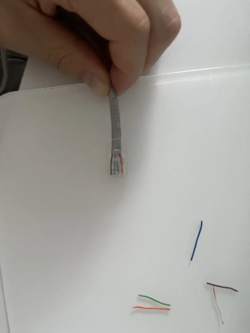
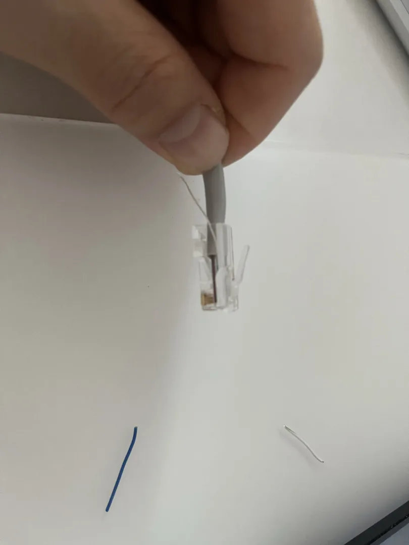
Push the wires into the plug until you can see the copper reach the very front, just behind the gold contacts. Look through the clear plastic — if any wire stops short, pull it out and start again. The jacket should seat inside the plug so the strain relief bites it, not the bare wires. This is the step most people get wrong: a wire that stops 2 mm short still looks fine from the outside, but the contact never bites it, and the cable fails intermittently.
Step 5 — Crimp
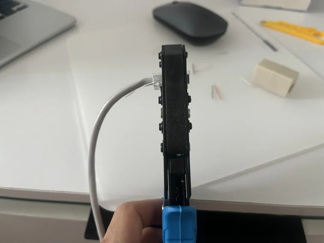
Seat the plug in the crimper and squeeze until the tool bottoms out — you will feel and hear a click. Crimp once, fully. A half-crimp is the most common cause of “it worked, then it stopped.” If the handle does not travel all the way down, the contacts did not fully pierce the insulation.
Step 6 — Test
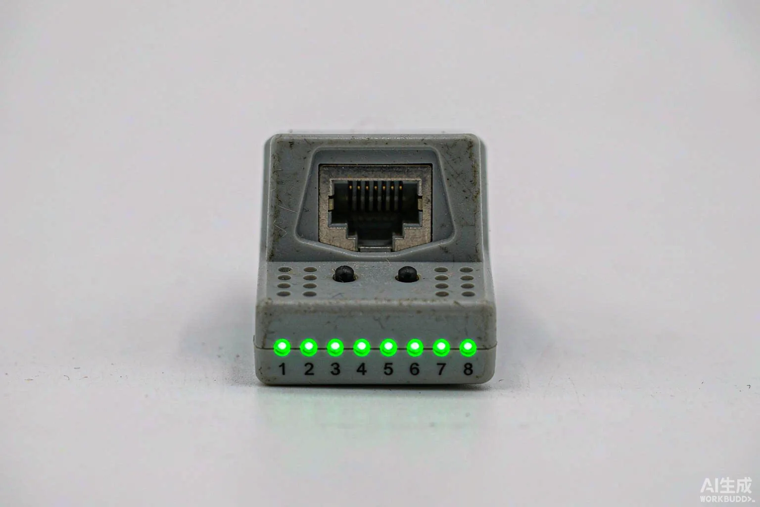
Plug both ends into a tester. All 8 lights should light in order, 1 through 8. Read the result in two steps: a dark light means that wire is open (the contact never bit, or the wire broke), and lights out of order means two wires are crossed (you arranged them in the wrong sequence). Either way, cut the plug off and start again — do not try to pull a crimped plug apart and reuse it.
The 5 Most Common Crimping Mistakes
| # | Mistake | Symptom | Fix |
|---|---|---|---|
| 1 | Wires not pushed to the end | Intermittent link, or Gigabit drops to 100 Mbps | Re-crimp with wires touching the front |
| 2 | Trimmed too long, copper exposed | Crosstalk, dropped packets at high speed | Trim to 12 mm, jacket seated in the plug |
| 3 | Untwisted too far | Crosstalk from destroyed twist | Keep untwisted section ≤13 mm |
| 4 | Different standard on each end | 100 Mbps may work, Gigabit fails | Use T568B on both ends |
| 5 | Not crimped fully | Wire pulls out, no link | Crimp to the bottom, or replace the tool |
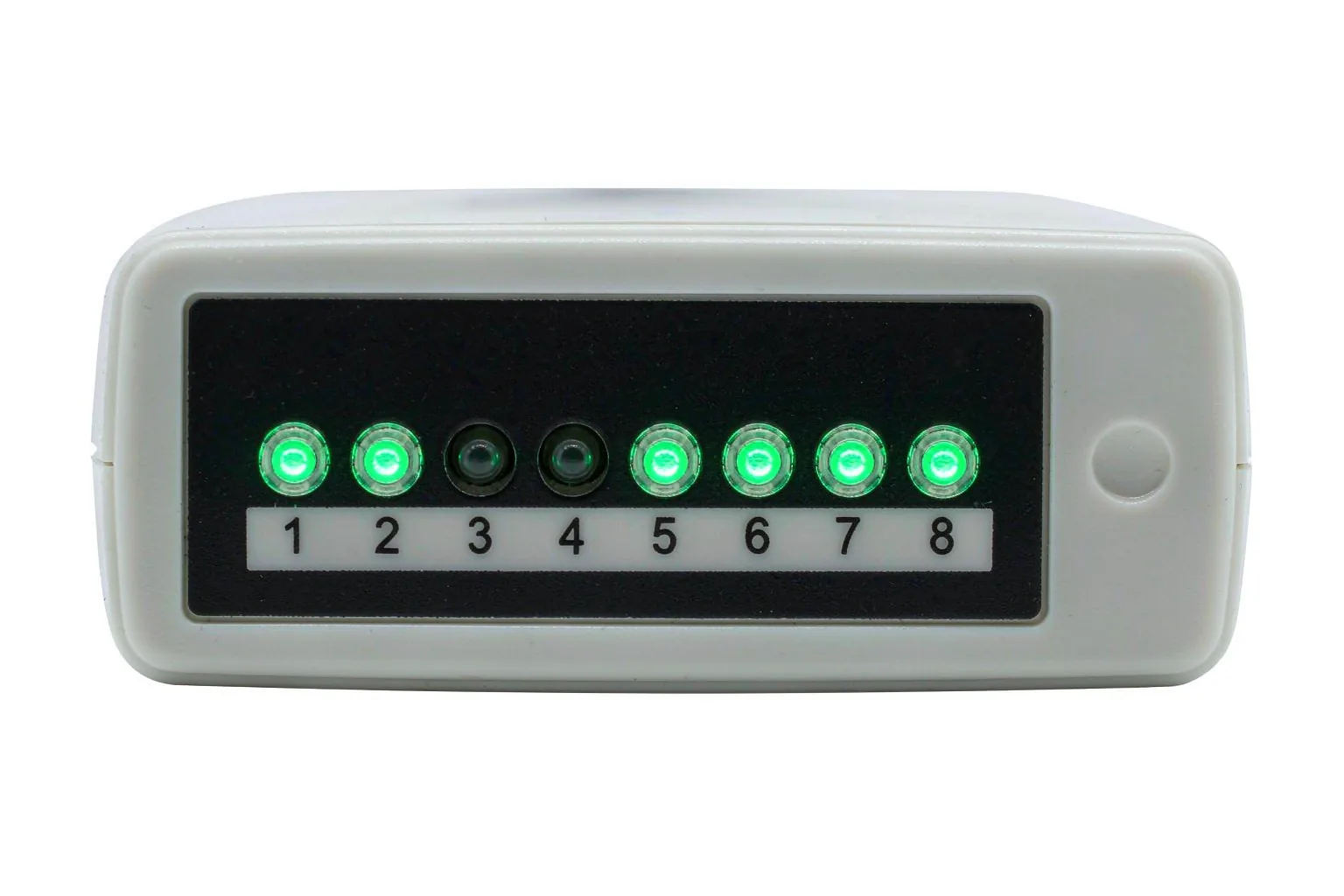
Mistakes 1 and 5 are the same failure viewed from two sides: the contact never bit the copper. If a cable works when you wiggle it and dies when you let go, that is the cause.
Straight-Through, Crossover, and Rollover Cables
- Straight-through — both ends the same standard. This is the default today; modern devices auto-correct (Auto-MDIX) anyway.
- Crossover — one end A, one end B. Used for old device-to-device links; rarely needed now.
- Rollover — the exact reverse order. This is a console cable for switch configuration, unrelated to A/B.
Cat5e vs Cat6 vs Cat6a: Does the Pinout Change?
The pinout is identical across all three. What changes is the cable construction and the frequency it can carry.
| Cat5e | Cat6 | Cat6a | |
|---|---|---|---|
| Frequency | 100 MHz | 250 MHz | 500 MHz |
| Speed / distance | 1G / 100 m | 1G / 100 m, 10G / 55 m | 10G / 100 m |
| Internal separator | None | Cross-shaped spline | Spline + heavier shield |
| Plug | Standard 8P8C | Standard 8P8C (staggered) | Dedicated shielded, pricier |
Upgrading to Cat6 does not make anything faster unless both devices also support 2.5G or 10G. The pinout stays the same; the copper inside gets better.
Frequently Asked Questions
Can I mix T568A and T568B on the same cable?
That makes a crossover cable. At 100 Mbps it usually still works because most devices auto-correct; at Gigabit it will often fail. Use one standard on both ends.
Why does 100 Mbps only use 4 wires?
100BASE-TX uses one pair to transmit and one pair to receive. Gigabit uses all four pairs in both directions at once, which is why it needs all 8 wires.
Does the pinout matter for a short patch cable?
Yes. A short cable can “work” while dropping speed and packets. A flaky short cable is harder to find than a dead one, so crimp it correctly the first time.
Is RJ45 the same as 8P8C?
In everyday speech, yes. Technically RJ45 is a telephone standard and 8P8C is the connector; the industry uses the names interchangeably.
Do I need a special crimper for Cat6?
A normal crimper works, but Cat6 conductors are thicker, so use a plug with a staggered (offset) layout — otherwise the contacts may not bite through.
What happens if I reverse the whole cable end to end?
If you wire pin 1 to pin 8, pin 2 to pin 7, and so on, you have made a rollover cable, not an Ethernet cable. It will not link two computers — it is a console cable used for switch configuration ports.
Can I reuse a crimped plug?
No. Once the contacts bite into the copper, the plug is spent. If a cable fails the test, cut the plug off and crimp a fresh one. Pulling a plug apart usually bends the contacts so the next crimp is unreliable.
Summary
RJ45 is 8 pins, two standards, one real difference: orange and green swap. Learn T568B, keep the untwisted section under 13 mm, trim to 12 mm, crimp fully, and test all 8 lights. Every cable you make after that is a cable you can trust.